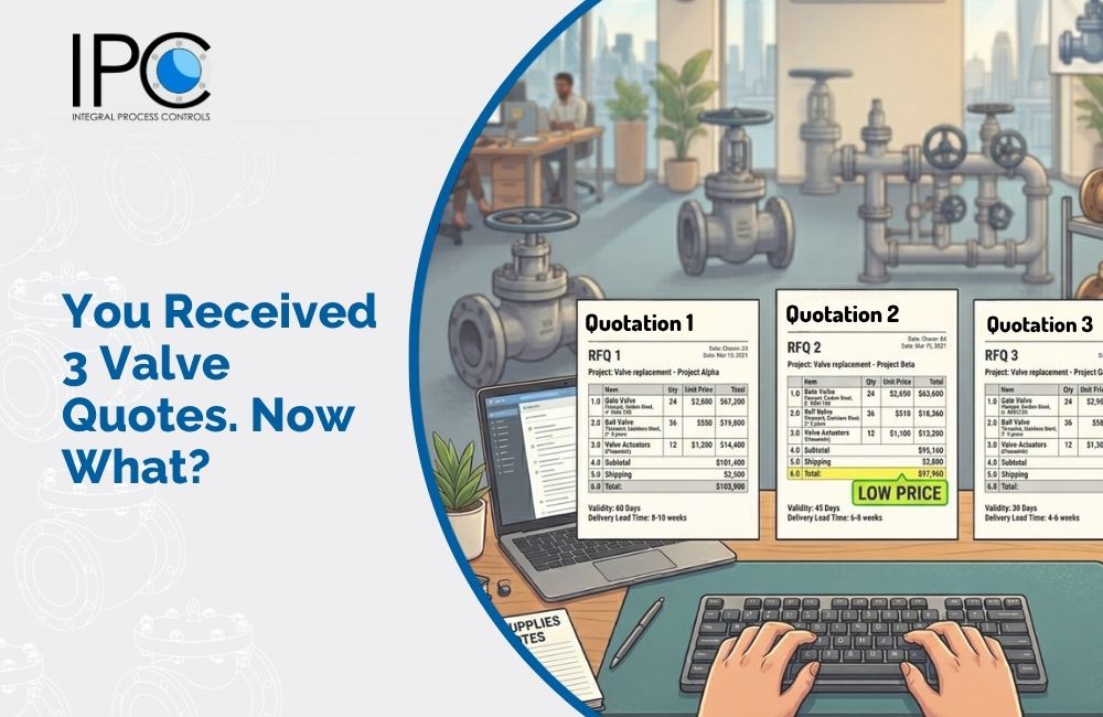
The lowest purchase price rarely means the lowest total cost. A cheap valve that leaks, sticks, or fails within two years will cost you far more in downtime, lost production, spares, and energy than a properly selected valve with a higher upfront price.
Life‑Cycle Costing (LCC) is the only rational way to compare valve options. It predicts the total cost of owning and operating a valve over a defined period – typically 5 years.
This guide breaks down the four main LCC drivers and shows you how to use them to justify better procurement decisions.
1. The Four Pillars of LCC
A complete LCC includes these cost categories:
Cost Category | What It Includes | What it significance |
Purchase Price | Initial valve + actuator cost | Often the smallest portion of 5‑year cost. |
Installation & Commissioning | Labour, alignment, testing | Poorly finished flanges = longer installation. |
Operating Costs | Energy to move the valve, leakage losses | High pressure drop = higher pump energy. Leaking = lost product. |
Maintenance & Downtime | Spares, labour, production loss from shutdowns | The biggest hidden cost. |
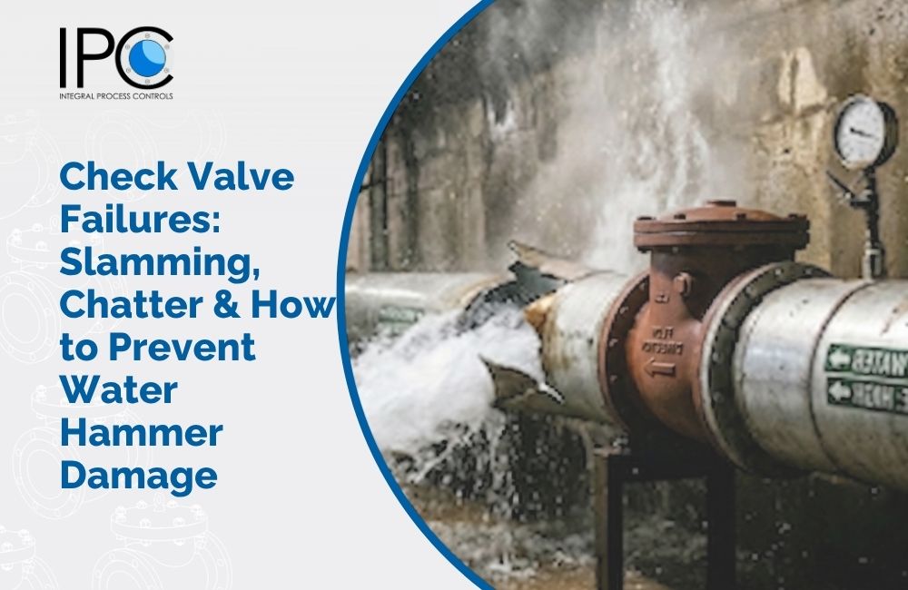
2. Downtime & Leakage Cost – The Hidden Giant
A single unplanned shutdown can cost more than a whole valve skid. Leakage has two costs:
- Direct cost: Lost product (gas, oil, chemicals).
- Indirect cost: Fugitive emissions penalties, safety risks, lost production time.
Example: A valve that leaks 1 kg/hour of steam at $10/kg costs $87,600 per year just in lost steam.
3. Spares & Maintenance Frequency – The Recurring Drain
Check the maintenance plan:
- How often must the packing be adjusted or replaced? (Carefully selected packaging material last much longer.)
- Are spare parts readily available? (Proprietary parts = long lead times.)
- How easy is it to change the seat? (Simple valve design makes a huge difference)
Rule: A valve that requires annual repacking costs more over 5 years than a valve that requires repacking every 3 years – even if the latter costs more initially.
4. Energy & Actuation Costs – The Power Drain
- Valve pressure drop: A poorly sized valve creates higher pressure drop – more pump/compressor energy.
- Actuator air consumption: Some actuators use more instrument air – adds to plant utility cost.
- Actuator size: An oversized actuator uses more energy per cycle.
Example: A ball valve with a pressure drop of 0.5 bar instead of 0.2 bar across the same flow wastes 60% more pumping energy.
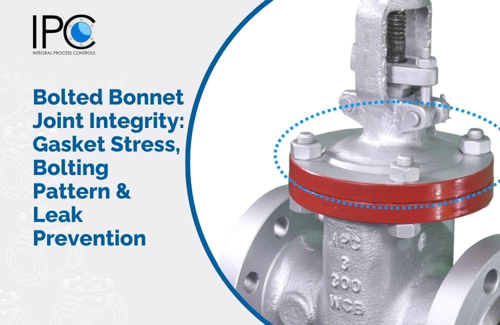
5. Failure Cost – The Catastrophic Hit
When a valve fails, the costs multiply:
- Failed seat: Cannot isolate – process must be shut down.
- Broken stem: Valve cannot operate – replacement required.
- Leaking bonnet: Emergency repair often involves premium labour rates and overtime.
A single major failure can cost 10X the valve price in lost production and repair.
6. Practical LCC Formula
To compare two valves, calculate:
Total 5‑Year Cost = Purchase Price + (Installation Cost) + (Annual Maintenance Cost × 5) + (Annual Leakage Cost × 5) + (Energy Cost × 5) + (Expected Failure Cost × Risk Factor)
Then compare the totals, not the purchase prices.
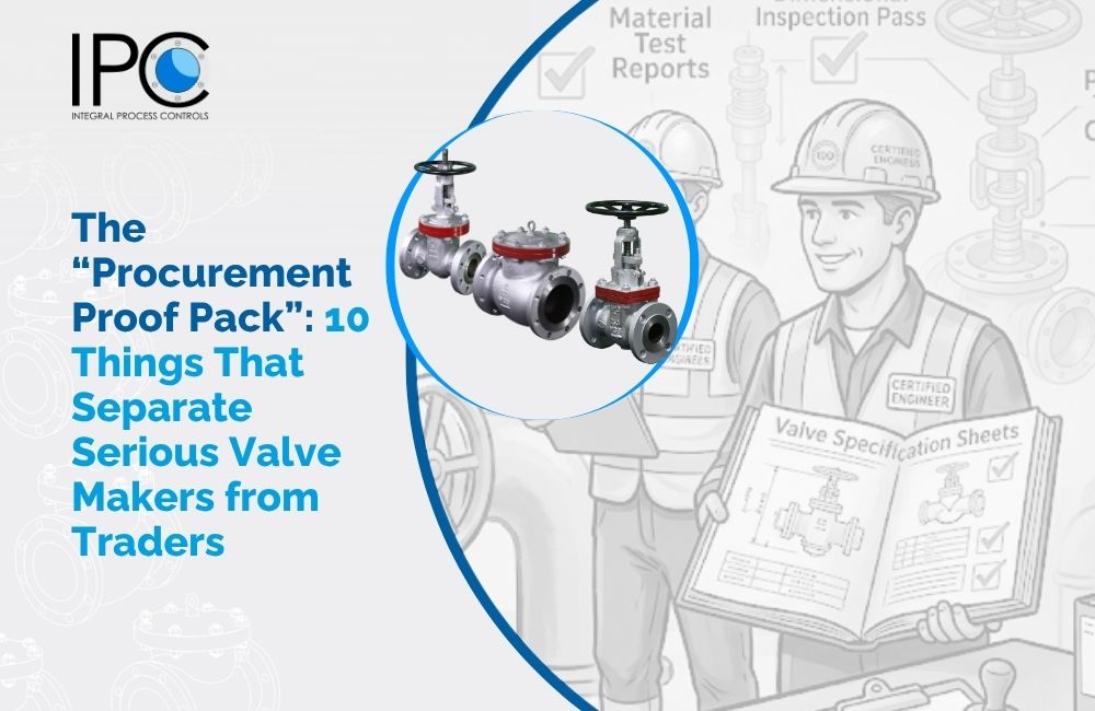
7. How IPC Helps You Reduce LCC
- Application‑driven selection: We recommend the right valve, not the cheapest.
- Low‑emission packing: Reduces leakage and fugitive emissions.
- Reliable materials: Longer life, fewer spares.
- Full documentation: Supports your maintenance planning.
- Spare parts availability: Stocked for fast delivery.
8. Your Next Step: Use LCC in Your Next Purchase
Before you sign a PO, request a 5‑year LCC projection from your supplier. At IPC, we provide a simple LCC comparison to support your ROI justification.