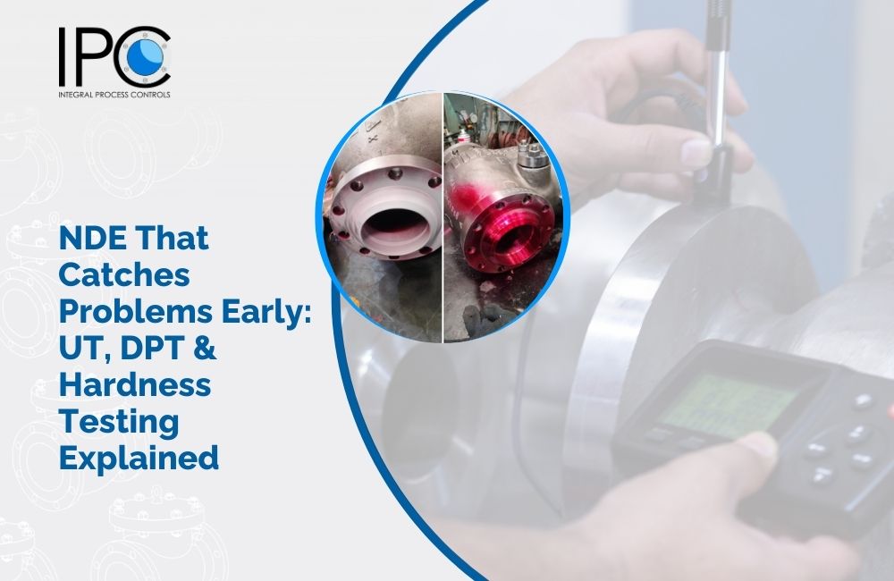
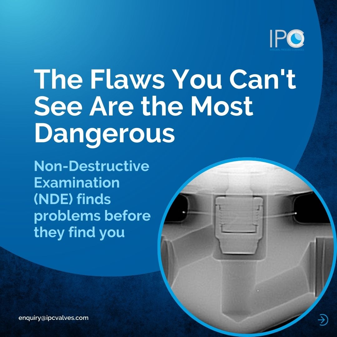
Why Seeing Inside Matters Before It's Too Late
In the industrial valve manufacturing, quality assurance isn’t just a final inspection it’s a proactive hunt for defects that could lead to catastrophic failure. Non-Destructive Examination (NDE) is the keys to preventive approach. Unlike tests that break or alter a component, NDE allows us to peer inside and scrutinize materials without causing damage, ensuring every valve meets the strictest integrity standards before it leaves the factory.
At IPC, our commitment to proven reliability and quality is built on a foundation of rigorous in-house QA/QC processes. With over two decades of experience serving critical sectors like oil and gas, power, and chemicals, we understand that the true cost of a valve isn’t just its purchase price, but the risk of unplanned downtime. This guide demystifies three essential NDE methods Ultrasonic Testing, Dye Penetrant Testing, and Hardness Testing and explains how we use them to deliver valves you can trust
The NDE Toolkit: Methods, Applications, and Acceptance Criteria
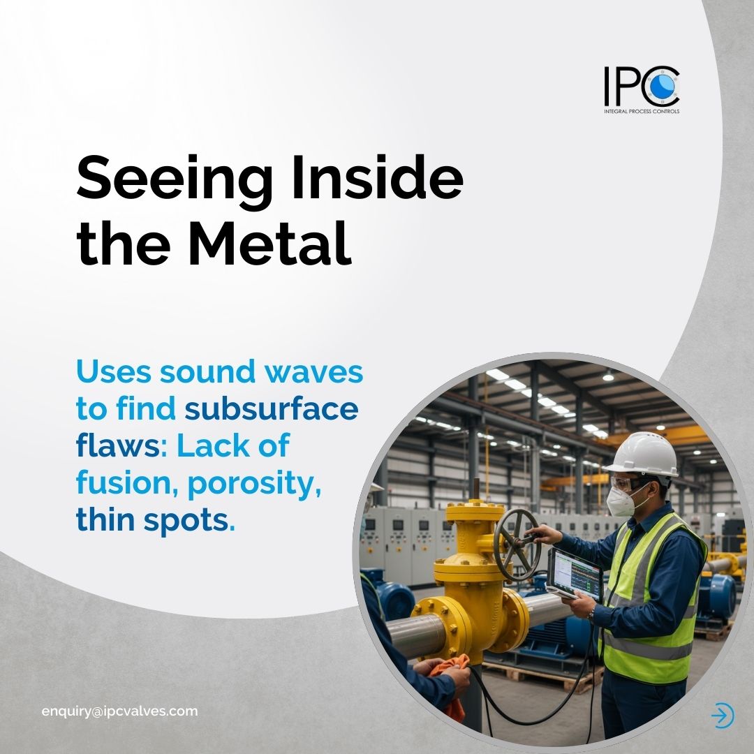
1. Ultrasonic Testing (UT): Seeing Beneath the Surface
What it Detects: UT is our primary method for finding subsurface flaws. It excels at identifying:
- Lack of fusion or incomplete penetration in welds.
- Internal voids, porosity, and inclusions.
- Laminations in base materials.
- Variations in material thickness (e.g., thin spots from corrosion or erosion allowance verification).
How it Works & Its Limitations:
A technician uses a probe to send high-frequency sound waves into the material. Reflections from internal discontinuities are displayed on a screen. While incredibly powerful for internal inspection, UT requires skilled technicians and couplant (a gel or fluid), and it can be challenging to use on complex geometries or coarse-grained materials.
IPC’s Application & Acceptance Criteria:
We utilize UT on critical weld joints for butt-weld end valves and on cast bodies for high-pressure service. Our criteria are based on ASME Section VIII and ASME B31.3, rejecting any indications that exceed the allowable size, length, or accumulation as per the referenced code.
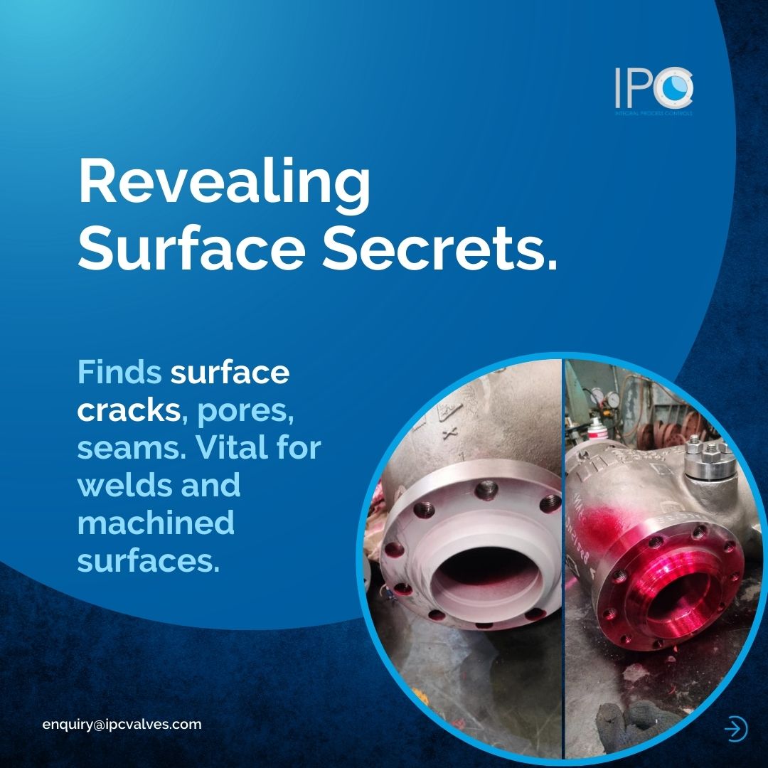


2. Dye Penetrant Testing (DPT): Exposing Surface Flaws
What it Detects:
DPT is the go-to method for finding surface-breaking defects that are often invisible to the naked eye, such as:
- Fine cracks (including heat-affected zone cracks in welds).
- Porosity open to the surface.
- Laps and seams in machined surfaces.
How it Works & Its Limitations:
A low-viscosity, colored dye is applied to the clean surface. It seeps into any surface openings via capillary action. After a dwell time, the excess is removed, and a developer is applied to draw the trapped dye back to the surface, revealing a clear visual indication of the flaw. DPT is excellent for non-porous materials but cannot detect subsurface defects.
IPC’s Application & Acceptance Criteria:
We apply DPT on all accessible surfaces of critical welds, valve stems, and machined seating surfaces. Acceptance is typically to ASME B16.34 and client specifications, where linear indications (cracks) are generally not permitted, and rounded indications (porosity) have strict limits on size and frequency.
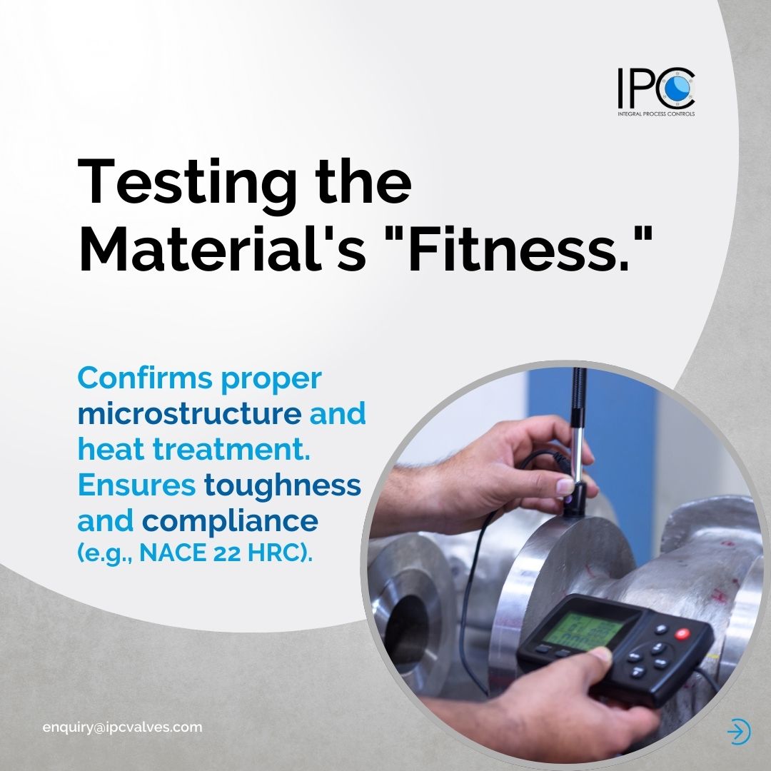
3. Hardness Testing: Confirming Material “Fitness”
What it Detects:
Hardness testing doesn’t find flaws like a crack. Instead, it measures a material’s resistance to indentation, which is a reliable indicator of:
- Proper heat treatment and microstructure confirmation.
- Absence of undesirable phases (e.g., sigma phase in stainless steels that embrittles them).
- Conformance to specified material grades (e.g., ensuring A105 meets its hardness range).
How it Works & Its Limitations:
Using portable (Brinell, Rockwell) or laboratory (Vickers) testers, a standardized indenter is pressed into the material under a specific load. The size of the indentation is measured to determine hardness. It provides a localized reading and must be performed at specified locations (e.g., weld, heat-affected zone, base metal) for a valid assessment.
IPC’s Application & Acceptance Criteria:
We perform systematic hardness traverses across weld qualifications (PQR/WPS) and on finished products for sour service (NACE MR0175) and other critical applications. Acceptance windows are defined by standards like NACE (typically 22 HRC max for carbon/low-alloy steels).
The IPC Quality Assurance Framework: NDE as a Standard, Not an Option
Our approach to quality is systematic. NDE isn’t a sporadic check; it’s integrated into our manufacturing workflow in our 25,000+ sq. ft. facility, overseen by a dedicated team of 150+ industry experts.
Procedure-Based: Every UT, DPT, and hardness test follows qualified written procedures in compliance with ASME Section.
Personnel Qualification: Our NDE technicians are certified to industry-recognized standards, ensuring consistent, reliable results.
Documented Evidence: The results of all NDE activities are meticulously recorded in our Manufacturer’s Data Records (MDR). You receive clear reports logs, charts, and certificates that provide full traceability and proof of compliance, making your project audits painless.
Conclusion: Specifying Valves with Verified Integrity
Choosing a valve supplier means trusting their commitment to uncovering potential problems long before they reach your site. By specifying IPC, you partner with a manufacturer that employs a multi-layered NDE strategy to validate weld quality, material properties, and surface integrity.
This rigorous, code-compliant inspection regime is what transforms a manufactured component into a reliable asset for your power plant, refinery, or chemical processing unit. It’s the technical assurance behind our promise of reliability, ensuring the valves we deliver are built not just to specification, but to last.